Network cables and fibre
Cat6 or Cat6A copper runs and optical links based on the chosen architecture.


Residential · Commercial · Large projects
Solid connections.
Well-orchestrated projects.
Cat6, Cat6A and fibre optic network cabling installation for homes, offices, retail spaces and large buildings. From Ethernet jacks to patch racks, let’s prepare the connections for your project.
Structured cabling installation
Structured cabling connects a building’s jacks and equipment to an organized distribution point. It prepares the connections for computers, IP telephony, Wi-Fi access points and compatible devices.
For your project in Montreal or the surrounding regions, Solution Alarme Plus prepares the cable routes, terminations and labelling. Whether it’s a home renovation, a new office or a multi-storey building, the installation follows the spaces and how they are used.
Cat6 or Cat6A copper runs and optical links based on the chosen architecture.
Jack locations, terminations and connection points for your devices.
Panels, patch cords and organized connections in the telecom room.
Link identification and testing, with the level of testing defined before the work begins.
Before · During · After
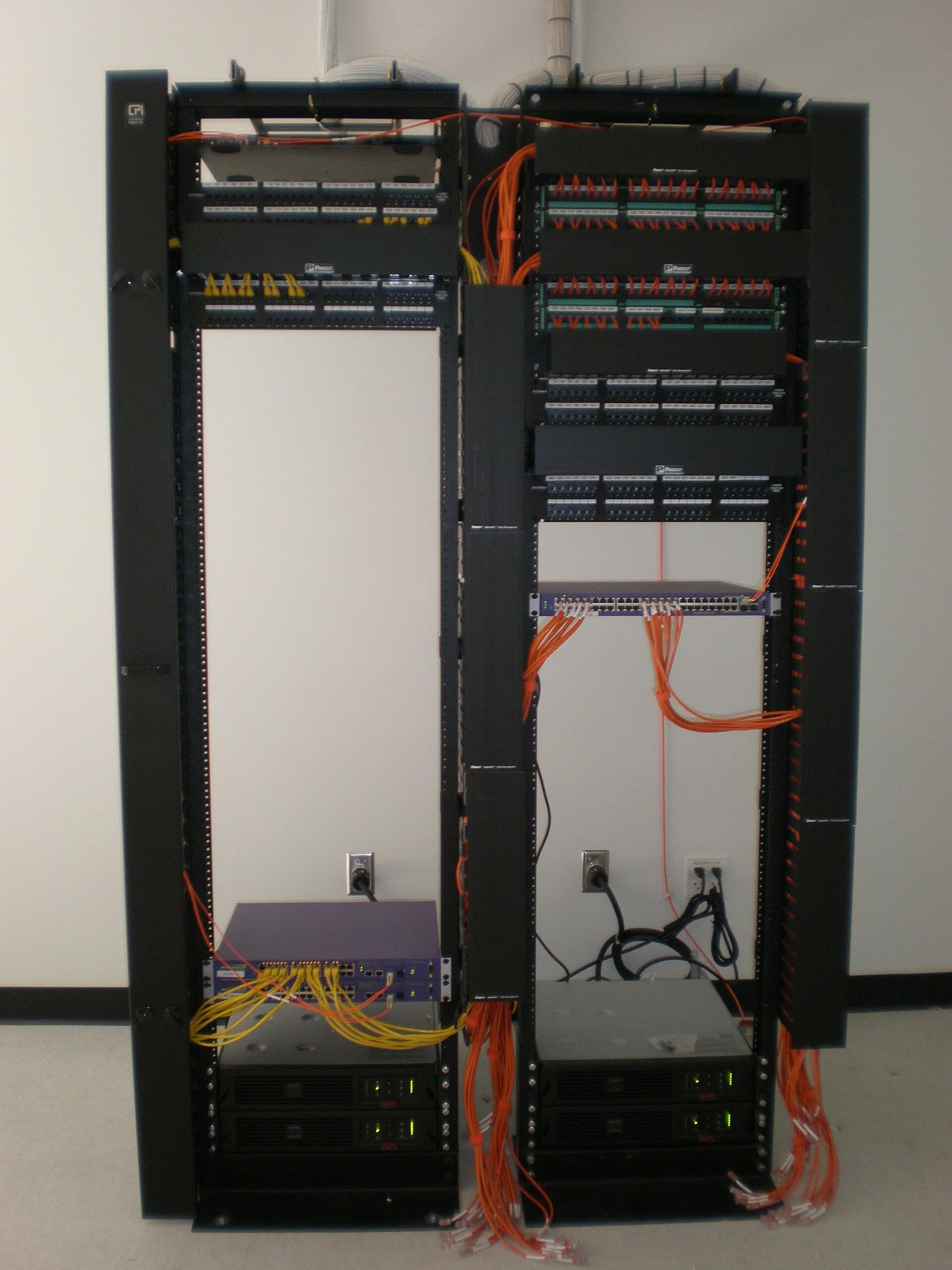
From identifying ports to tidying patch cords: a visual example to understand how a network rack gets reorganized.
Illustrative example — three AI-generated images. This sequence does not show a job completed by Solution Alarme Plus.
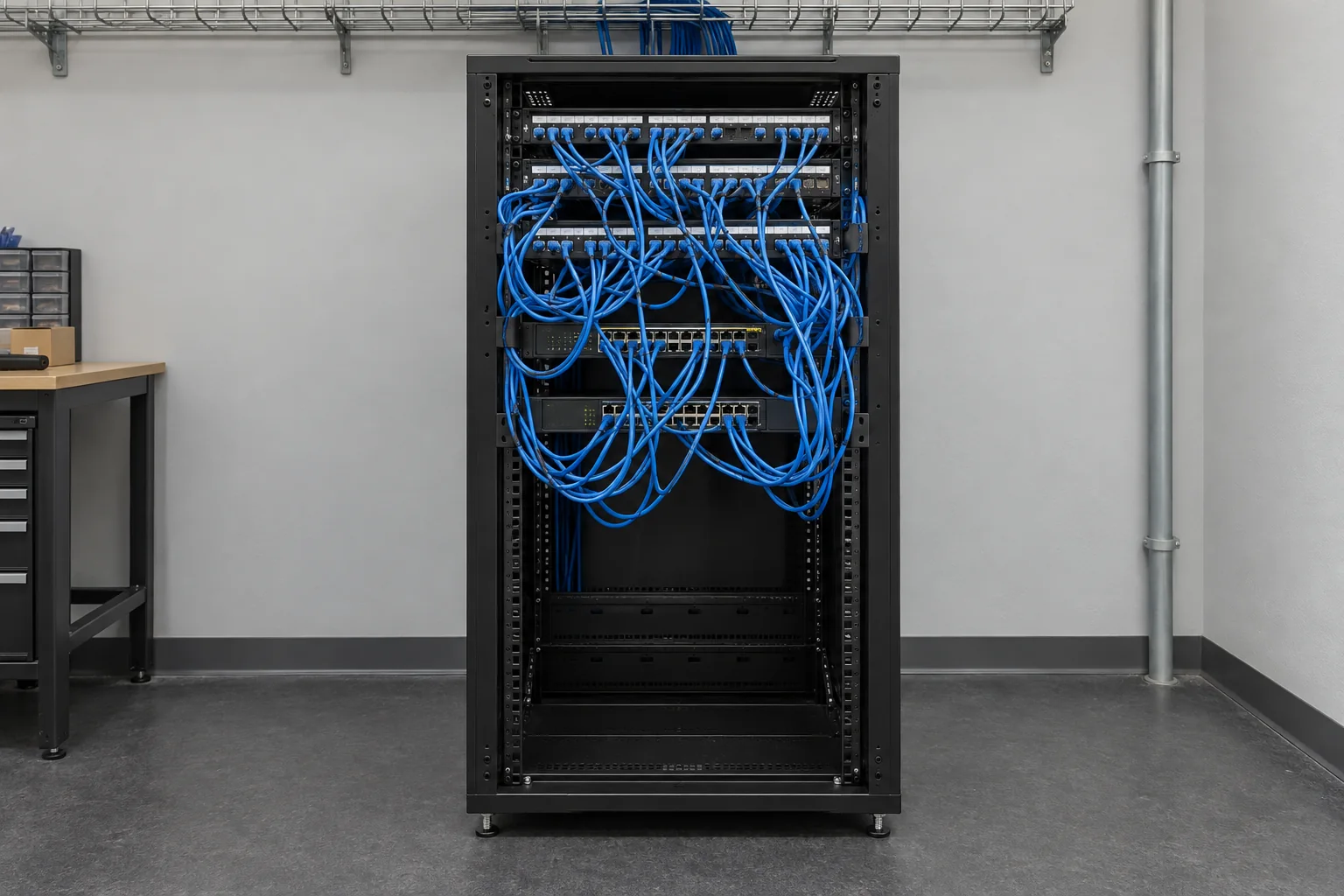
Record the connections, the ports in use and the devices that must stay in service. Crossed patch cords make it hard to reach the equipment.
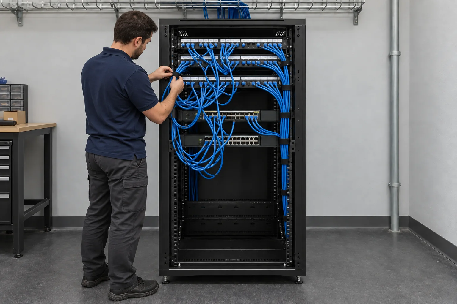
Choose suitable lengths, route the patch cords and label the ports. Each cutover follows the agreed access times and service interruptions.
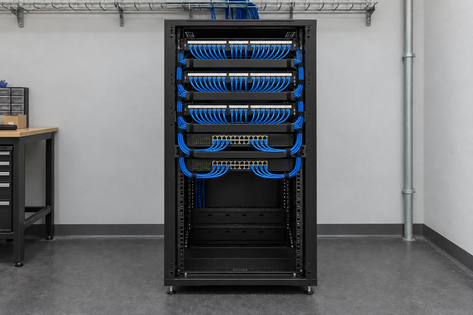
An organized layout that makes identification and access easier. The port map and the results of the planned tests are delivered as set out in the contract.
A tidy rack does not, on its own, prove link performance. The level of verification, qualification or certification is defined before the work begins.

Houses · Condos · Apartments
A desktop computer in the office, a TV in the living room and Wi-Fi access points between floors don’t have the same needs or locations. Planning Ethernet jacks lets you connect fixed devices and prepare links for access points.
In new construction, cable routes are prepared before the finishing work. In an existing home, we look at access through the basement, attic, ceilings or suitable surface-mounted routes.
Offices · Retail · Business premises
New office, move or expansion: the connections follow the workstations, meeting rooms and business equipment. Choosing Cat6 or Cat6A depends on bandwidth needs and planned growth.
Ethernet jacks for workstations, IP phones, printers and meeting rooms. Links and any PoE power follow the selected equipment.
Links to access points, checkouts and compatible surveillance cameras.
Network rack, panels, patch cords and connection labelling.
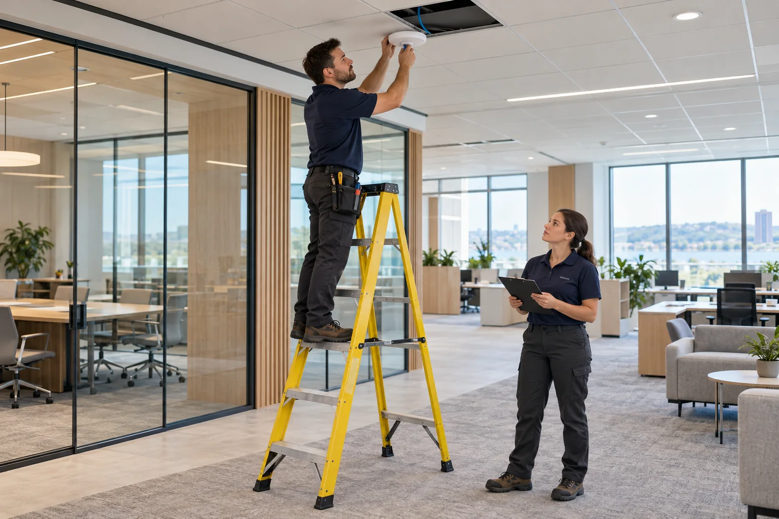

Buildings · Warehouses · Large projects
A large building requires planning the areas to serve, the telecom rooms, the distances and site access. Backbones between floors or rooms can use copper or fibre optic depending on the architecture and equipment.
In an occupied building, schedules and cutover steps are prepared with the people responsible for the site. Work in new construction or renovation follows the constraints of the job site.
Concrete configurations
Illustrative scenarios: they explain how a network is prepared and do not show completed client jobs.

Illustrative example · Retail store
For a store with three checkouts, two IP cameras and one Wi-Fi access point, the plan separates the counter connections, the overhead points and the distribution cabinet.
The Internet connection, payment terminals and device settings are coordinated with the relevant providers.
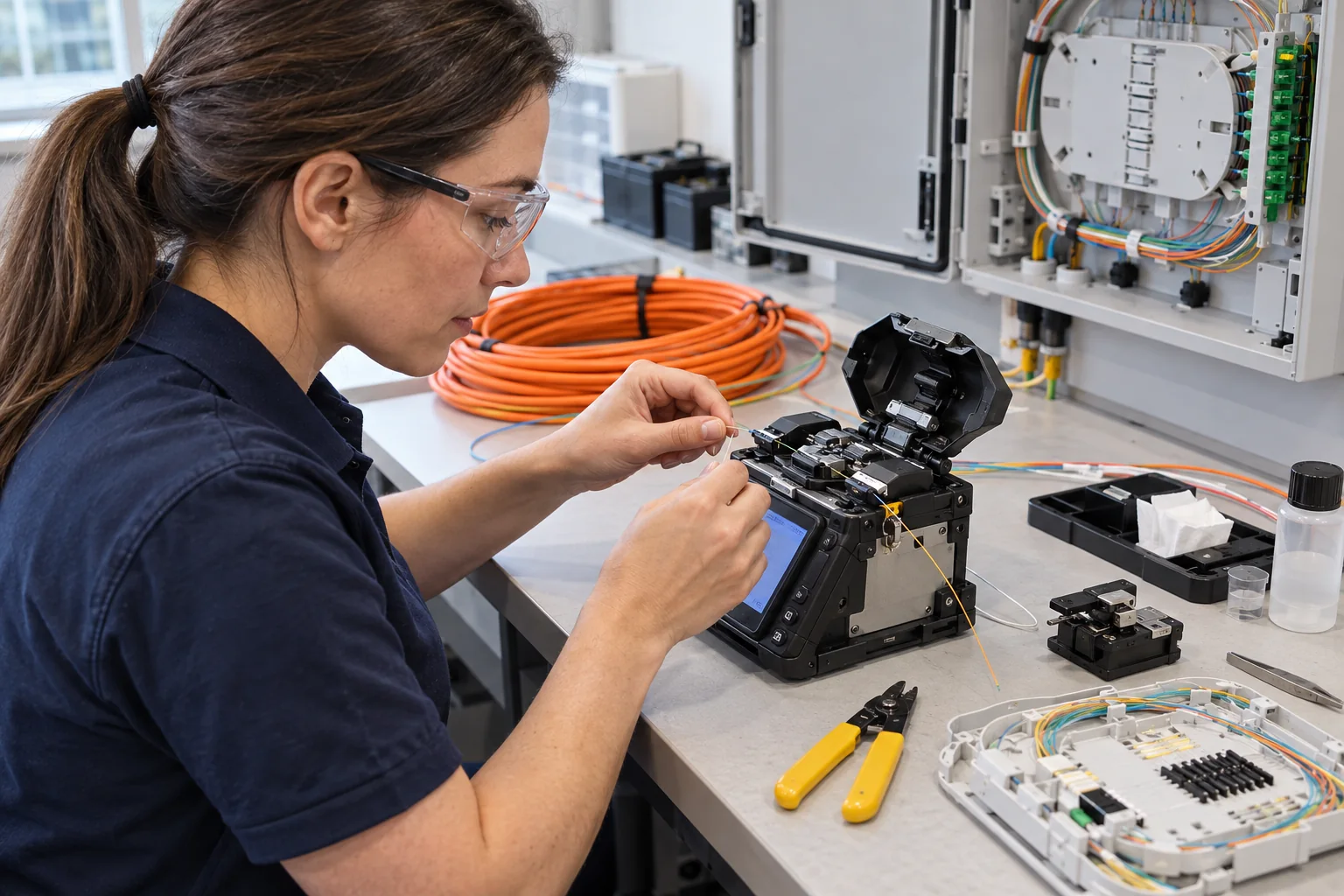
Illustrative example · Three-storey building
One configuration can link the telecom rooms with fibre optic, then distribute each floor’s jacks over Cat6 or Cat6A copper. The architecture depends on distances and equipment.
Fibre type, optical interfaces and testing level are defined for the building.
Choose based on your network
The right cable depends on distance, devices and the capacity you need. Jacks, panels and patch cords must also match the chosen system.
An option to consider for home and office jacks aiming for a Gigabit network. Performance depends on the entire link and how it is terminated.
For an architecture targeting 10 Gigabit over a 100 m channel. Also plan for the components, routing space and required level of testing.
Worth considering for backbones, links between telecom rooms, some long distances or capacity needs. Fibre type and interfaces are chosen together.
Real equipment photographs
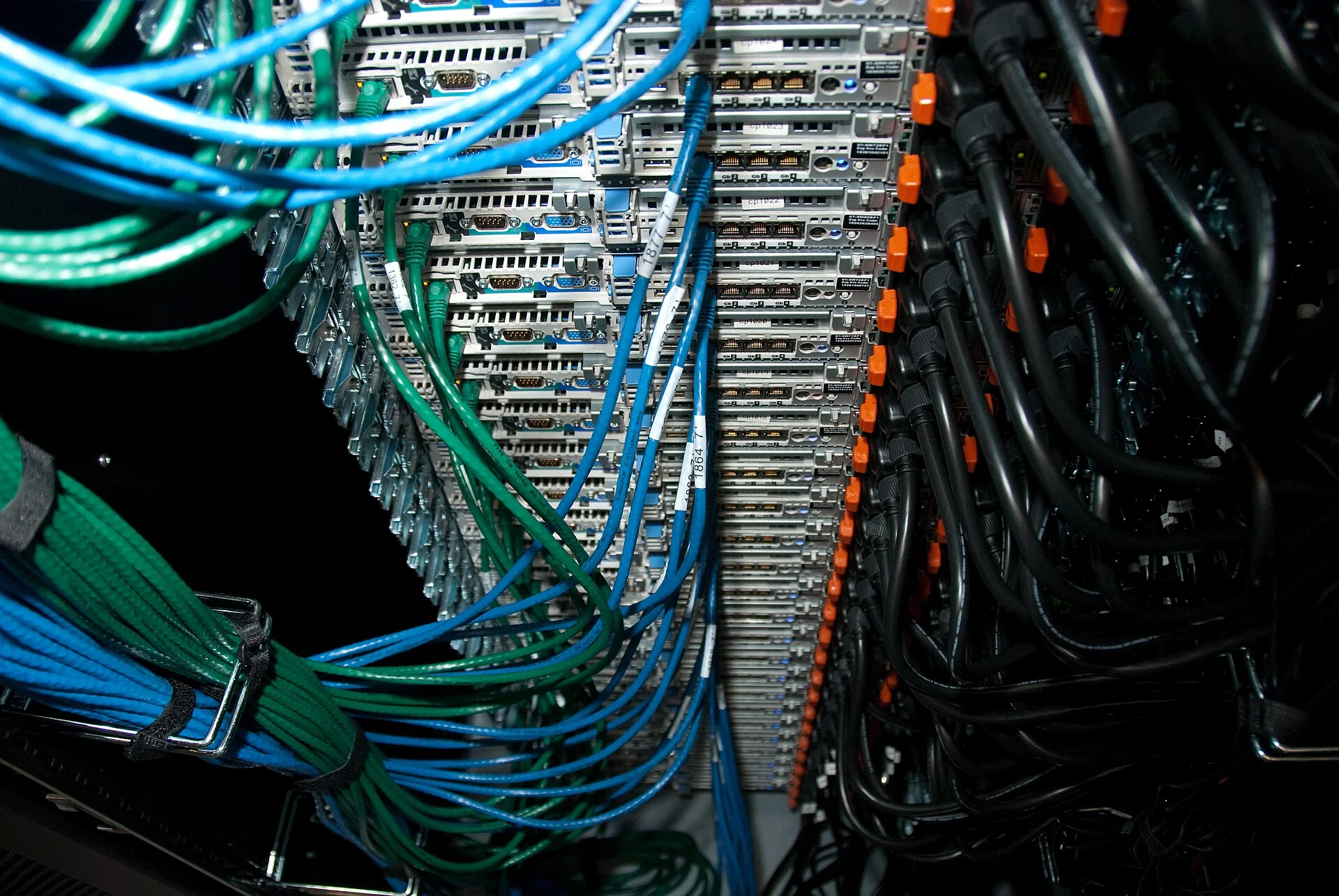
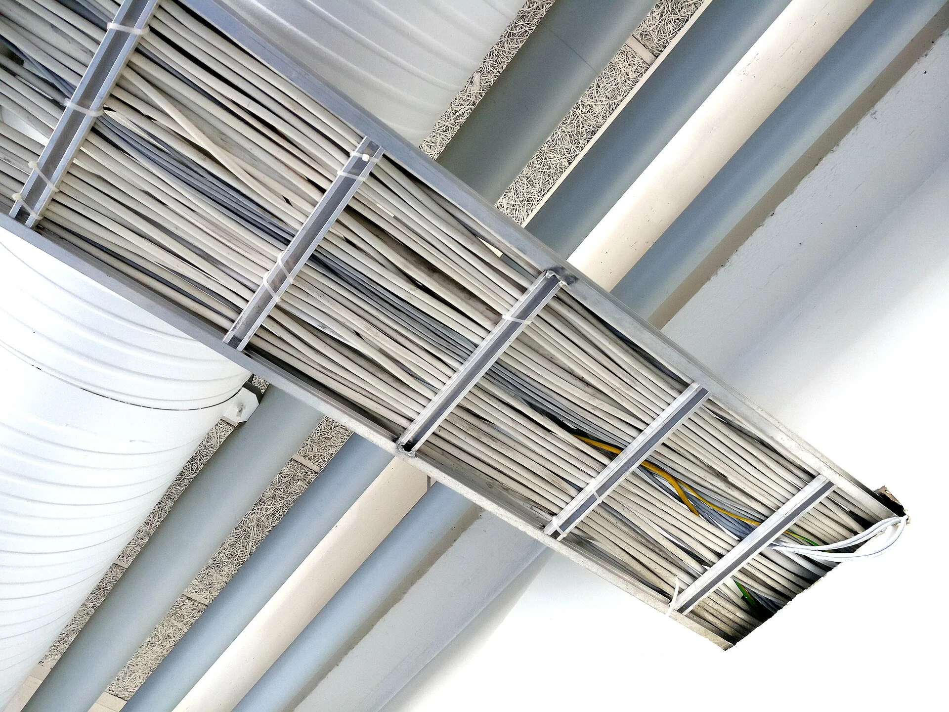
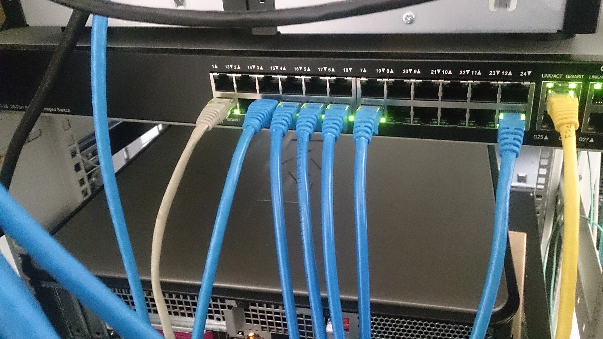
Six illustrative photos to help you recognize the parts of an installation. Select an image to enlarge it.

Planning · Installation · Documentation
The number of jacks alone isn’t enough to prepare a job. We look at how the spaces are used, the cable routes, access to technical areas and the steps to coordinate with the building managers.
The scope also specifies the equipment to connect, the configurations to leave to your IT team and the results to deliver after the agreed tests.
Discover Solution Alarme Plus
Building, devices, plans and required capacity.
Locations, pathways and job site organization.
Cables, jacks, panels and link patching.
Port mapping and results set out in the contract.
Where your installation is
Tell us the city and the building’s address so we can confirm service availability. Travel, access and timelines depend on the project.
Houses, condos, offices and commercial spaces: cable routes follow the available spaces and connection needs.
Our services in Greater Montreal ↗Construction, renovation or expansion: prepare the pathways and central point before terminations.
Our services on the North Shore ↗A house, a store and a warehouse each call for different locations and network distribution.
Our services on the South Shore ↗Location, job size and steps are reviewed before confirming installation terms.
Our services in Quebec City and Ontario ↗Frequently asked questions
Network cabling cost, installation timelines, work in finished buildings and documents to prepare: answers to the most common questions.
The number of links, their length, access, cable type, terminations, equipment, testing level and finishing work. Occupancy and job site constraints also count. A quote tailored to the building is more useful than a generic price per jack.
Duration depends on the number of links, the routes, access to technical spaces and the terminations required. Occupancy hours, finishing work and any network cutover also play a role. Tell us your target date: the timeline will be confirmed after the project is assessed.
The contract specifies cable pulling, jacks and terminations, panels or racks, labelling and the agreed tests. Equipment, finishing work, router or Wi-Fi configuration and certification reports must be detailed in the quote so you know what’s included.
Often, but the route depends on access to ceilings, basements, attics, shafts and walls. Raceway or a surface-mounted route can be an option when a concealed route is difficult. Any openings and finishing work must be specified before the work.
A floor plan, the list of rooms and devices, the number of connections you want and photos of the existing setup. Add your bandwidth goals, possible access, timeline and the level of documentation expected. If you don’t have all of this, start by describing your project.
Houses, condos, apartments, offices, stores, multi-unit buildings and warehouses: each project is assessed based on the devices, areas to serve and possible cable routes. New construction, renovation and occupied buildings each call for different methods and preparation.
Tell us the city and the building’s address, whether it’s in Greater Montreal, on the North Shore, on the South Shore, in Quebec City or in Eastern Ontario. Service availability, travel and timelines are confirmed based on the location and scope of the project.
Count the devices that would benefit from an Ethernet connection and reasonable future needs. An office with a computer, IP phone and printer isn’t planned like a bedroom. Furniture and device placement also determine jack locations.
It’s a consistent organization of a building’s cables, jacks, panels and termination points. It lets you match each jack to an identified link and connect equipment to the central point, instead of piling up connections that are hard to trace.
Yes, when several rooms or devices need to be connected: remote work, TV, gaming, Wi-Fi access points and IP cameras. The number of jacks depends on your use, the layout of the house and possible cable routes. A small central point can be enough for a residential installation.
The choice depends on target bandwidth, budget, distances, installation constraints and planned growth. Cat6A suits an architecture targeting 10 Gigabit over a full 100 m channel. For other needs, Cat6 may be a good fit. Every component in the link must match the chosen category.
Its condition, terminations and capacity for the intended use need to be checked. An existing link can work for Gigabit use when it’s suitable. However, a Cat5e label or a link light does not, on its own, tell you the full quality of the link.
90 m is the usual limit for a copper permanent link. The full channel can reach 100 m including patch cords. Length is measured along the actual route, including rises and slack, not just the distance between two points on a plan.
The two work together. Fixed devices can use Ethernet, while phones and tablets use Wi-Fi. Wi-Fi access points can themselves be connected by cable. Coverage depends on their placement, obstacles and network configuration.
Some mesh systems accept an Ethernet link between units, called wired backhaul. Check for this feature in the model’s documentation and follow its topology. Preparing jacks where the units will go makes this option possible.
No. The model must be compatible with the PoE type and power supplied. You also need to check the switch’s total power budget and link quality. Some cameras use a separate power supply or have specific requirements.
Fibre can make sense for a backbone between telecom rooms, a long distance or high capacity. The choice depends on distance, bandwidth, route and equipment interfaces. It doesn’t automatically replace every Ethernet jack in a home or office.
A panel centralizes terminations and makes identification easier. The mount can be compact in a home or small office. A larger rack is justified with more ports and equipment. Depth, ventilation, load and accessibility all factor into the choice.
The project must be assessed based on the route, distance, environment and available infrastructure. Choosing an outdoor cable or a fibre link depends on these constraints. A solution designed for an indoor room shouldn’t automatically be reused between two buildings.
No. Continuity and wiremap checks verify the terminations. Qualification assesses support for an application, and certification verifies parameters against a specific test limit. If a certification report is required, mention it when you request your quote.
Cabling and equipment configuration are separate items. The contract should specify device connections, switch, router and Wi-Fi settings, as well as the responsibilities of your Internet provider or IT department.
Understanding your installation
Cat6, Cat6A, fibre optic, jacks, Wi-Fi, PoE and testing: open the topic you’re interested in to find explanations and equipment photos.
Understanding your network
Structured cabling organizes a building’s communication links. Room jacks and connection points run back to a central location: a communication panel, a small cabinet or a network rack. Each link can then be identified and connected to the right equipment.
The goal: connected workstations, well-placed Wi-Fi access points, IP cameras powered according to their needs and an installation that can be understood, maintained and expanded.
Plan jacks and links based on actual use: office, TV, checkout, printer, camera or access point.
Group terminations, label cables and keep equipment accessible for changes and troubleshooting.
Anticipate new equipment, available ports and cable pathways while the building is accessible.
Your provider delivers the Internet connection. The wired network distributes it through the building. Wi-Fi lets wireless devices access it. Improving the cabling can fix a local link problem; it does not, on its own, change the speed of your Internet plan.
Residential structured cabling
Remote work, entertainment, Wi-Fi coverage and security: a home network is planned around your daily life and access to walls, ceilings and technical spaces.
Plan an Ethernet jack near the workstation, a link for the network printer and, if needed, several connections to avoid cords running across the room. A wired link helps stabilize local traffic and video calls when the rest of the network is suitable.
Bring the network close to the TV stand or entertainment room. The TV, console and media player can be connected directly or through a small switch, depending on the number of jacks and devices.
Prepare network drops for ceiling- or wall-mounted access points. For a compatible mesh system, an Ethernet link between units can carry traffic without relying solely on a wireless relay.
Plan routes to entrances, the garage or areas to monitor. PoE compatibility, distances, outdoor conditions and the recorder location are checked before choosing the cable and equipment.
Before the walls are closed is the time to plan jacks, pathways and spare capacity. In an existing home, possible routes depend on the attic, basement, ceilings and finishes to preserve.
Define private and common areas, the service entry point and how each network is managed. Routes through common areas and access to technical rooms must be coordinated with the people in charge.
Choose an accessible location suited to the equipment: provider entry, router, small switch and patch panel. Plan for power, room for patch cords and the necessary ventilation. A router enclosed in a metal panel can also limit Wi-Fi coverage, so access points must be positioned accordingly.
Commercial structured cabling
An opening, a move, an expansion or premises to reorganize: the network must follow the workstations, equipment and constraints of your business.
The number of employees isn’t enough to size a network. You also need to count IP phones, printers, meeting rooms, Wi-Fi access points, cameras, checkout systems and technical equipment.
A jack plan lets you match each location to a patch panel port. Rack space, switch ports, PoE power and links between zones are planned together.
Fixed workstations, IP telephony, shared printers, video conferencing and room booking: lay out jacks based on furniture, screens and presentation equipment.
Prepare connections for checkouts, Ethernet-compatible terminals, management workstations and cameras. Plan device locations and opening hours to limit interruptions during a migration.
Connect ordering systems, network printers, points of sale and Wi-Fi access points. Separating the guest network from management equipment is then handled in the network device configuration.
Take into account long distances, shelving, heights and the environment. Access points and cameras may require different routes; a fibre link can be considered between distant zones.
Organize management links, cameras and common-area networks. Clarify responsibility for private networks, access to shafts and permissions before any work.
Consider a backbone between telecom rooms, then distribution to users. Copper or fibre is chosen based on distances, target bandwidth, environment and equipment interfaces.
Network cable categories
Performance depends on the entire link: cable, jacks, panels, patch cords and termination quality. The category printed on a spool is not enough to guarantee the result.
| Category | Performance benchmark | Project to consider |
|---|---|---|
| Existing Cat5e | Gigabit Ethernet depending on the condition and compliance of the link. | Assess and test the existing cabling before deciding to keep or replace it. |
| Cat6 | Up to 250 MHz. 1 Gb/s over a 100 m channel. | Residential jacks, offices and equipment whose needs match this level. |
| Cat6A | Up to 500 MHz. 10 Gb/s over a 100 m channel. | Projects targeting 10 Gigabit, new capacity needs or planned network growth. |
Cat6 and Cat6A benchmarks: copper systems Leviton Cat6 and Cat6A. Actual throughput also depends on the devices and their configuration.
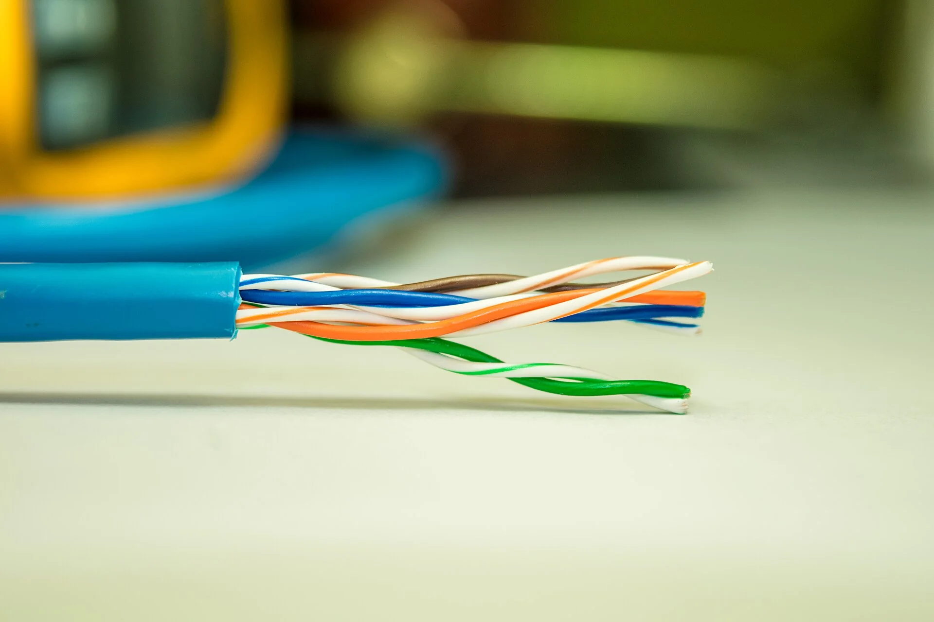
For a standard copper link, the usual permanent link limit is 90 m. It covers the fixed cabling and its terminations, without the equipment patch cords.
The channel can reach 100 m including patch cords. Measure the actual route, rises and slack, then choose another architecture if the planned distance exceeds what copper can handle.
Reference: Fluke Networks — permanent link and channel.
U/UTP refers to a cable with no shielding; F/UTP has an overall foil screen. The choice depends on the environment and termination system. A shielded system requires proper shield continuity and grounding.
The jacket is chosen for the planned route: indoor, humidity, UV or special conditions. For a detached garage or a link between buildings, distances and route constraints must be assessed before choosing a solution.
Choose identifiable products and compatible components. Copper-clad aluminium (CCA) conductors don’t have the same electrical properties as copper, which matters especially for PoE power.
The parts of the installation
Network quality is also built through terminations, patch cords and equipment organization. Here’s what you’ll find in a structured installation.
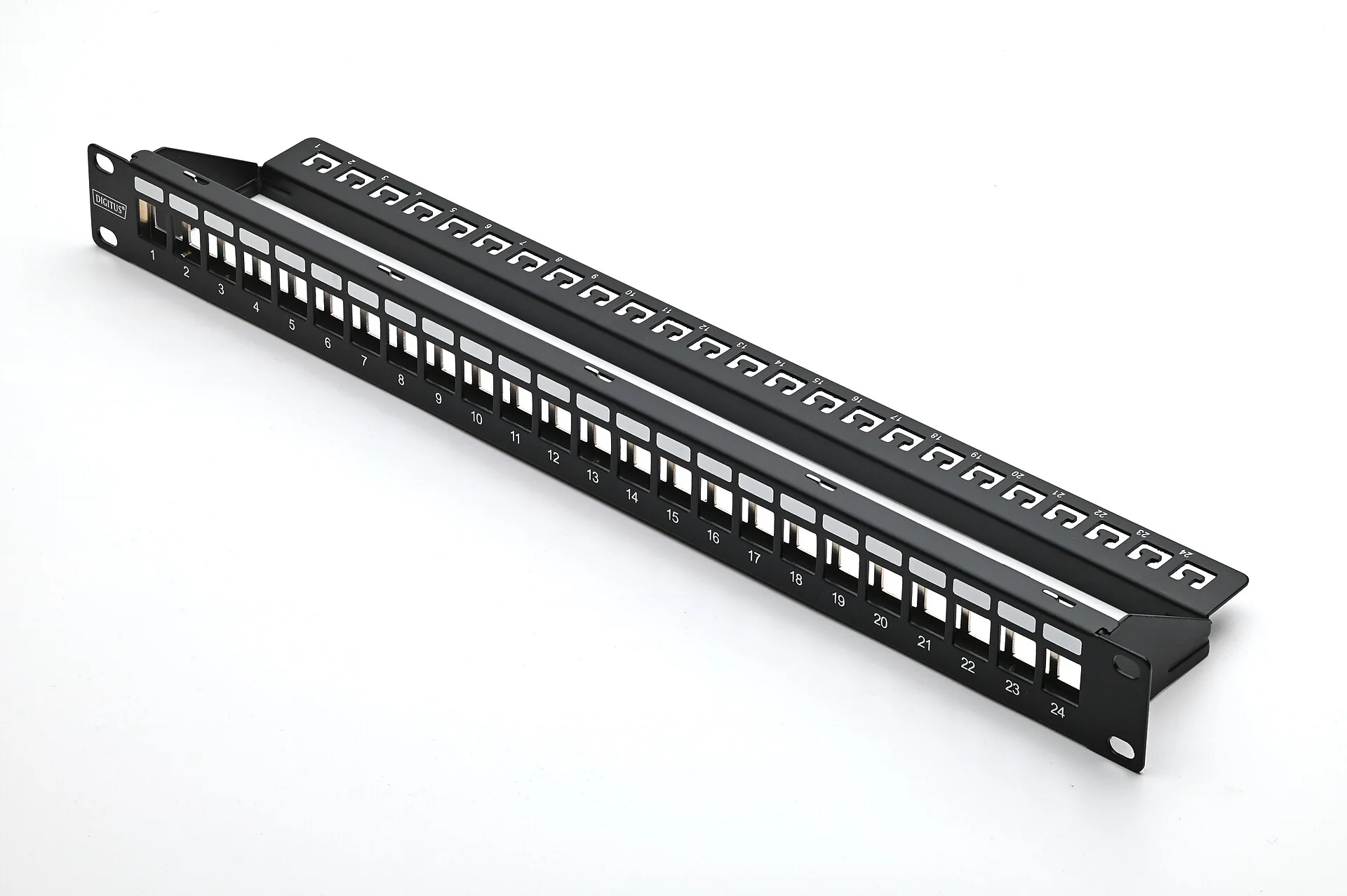
Fixed cables terminate on a panel. Patch cords then connect the required ports to the switch. This setup makes workstation changes and tracing a link easier.
The panel’s capacity, category and modules must match the project. Port numbering should follow jack numbering.
See the panel in the galleryThe switch connects devices to each other. Its number of ports, their speed, its management features and its PoE capacity must be chosen based on the devices to connect.
The router plays a different role: among other things, it connects the local network to the Internet. Replacing the cabling doesn’t replace the configuration of this equipment.
A home or small premises can use a compact termination point. A business with more equipment may need a wall-mount or floor-standing rack, with cord management and access to terminations.
Plan for depth, load, ventilation and working space. The mount must remain accessible for future changes.
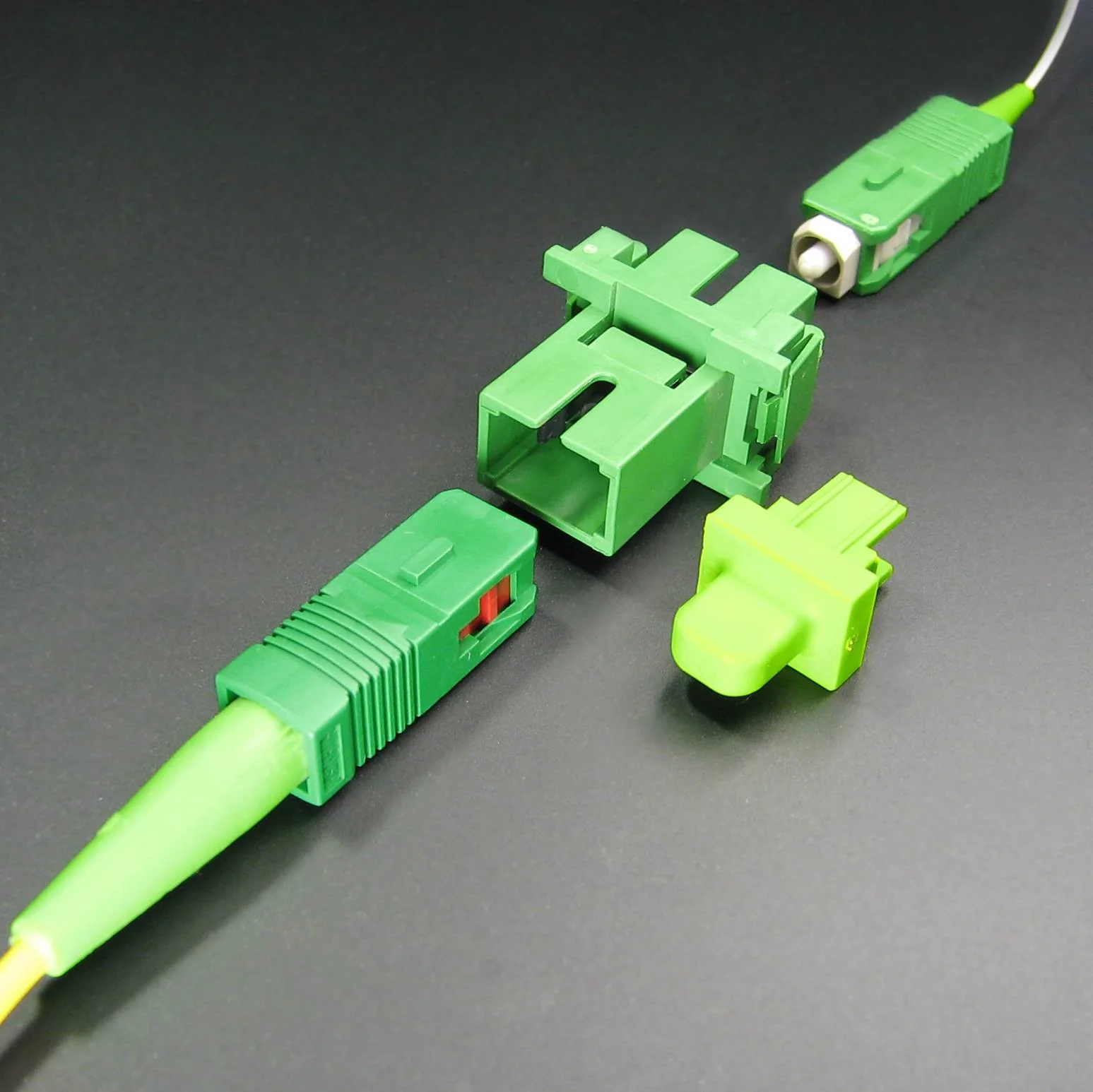
For copper, RJ45 jacks and patch cords must suit the chosen category. For fibre, connectors, patch cords and optical modules must match the fibre type and the interfaces used.
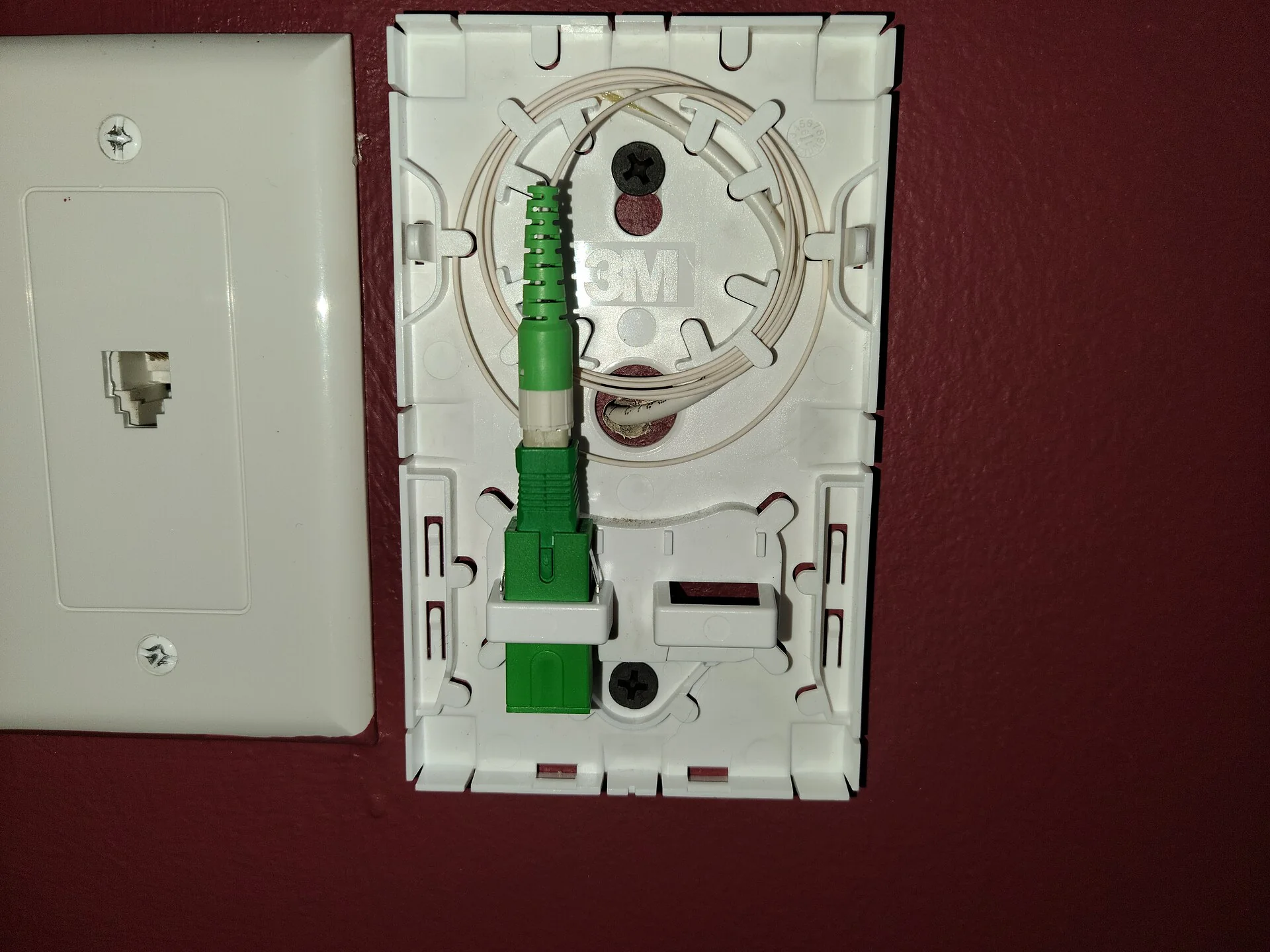
An SC connector, shown here, and an LC connector are different formats. Polish compatibility and optical components must also be checked.
Fibre optic and building links
Fibre is considered for backbones between telecom rooms, longer links or capacity needs. The choice starts from the route and the equipment to connect.
Single-mode fibre is an option for links whose distances and growth justify this architecture. Optical modules must be compatible with the speed, wavelength and power budget of the link.
Multimode fibre is commonly found in building and equipment room links. Possible distances depend on the fibre type and the Ethernet application: an OM3 or OM4 rating alone doesn’t guarantee a speed at any distance.
Plan the strands needed, spare capacity, fibre drawers and connections to switches. Choosing between a pre-terminated link and on-site terminations depends on the routes and project conditions.
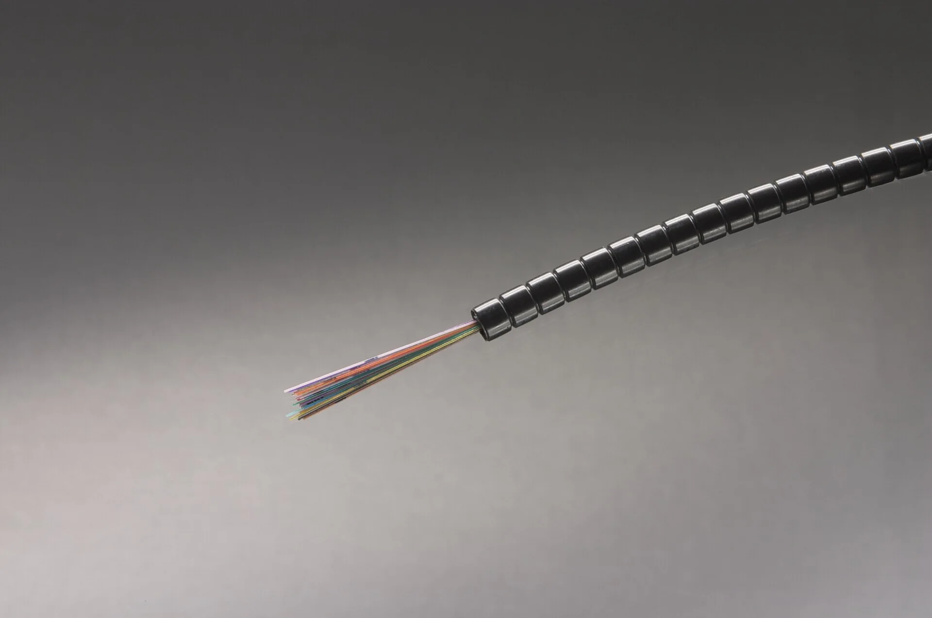
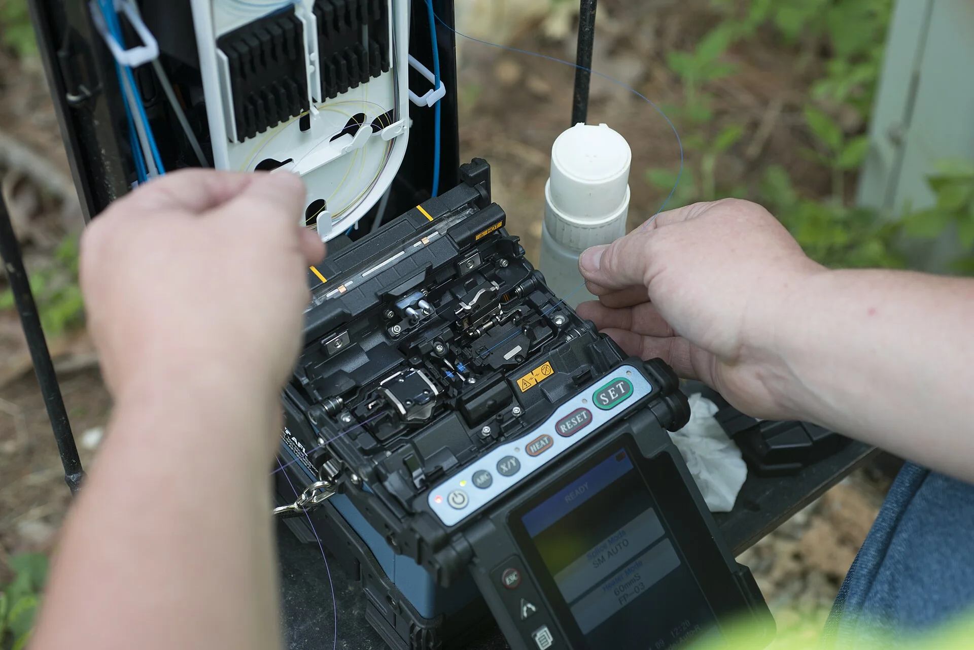
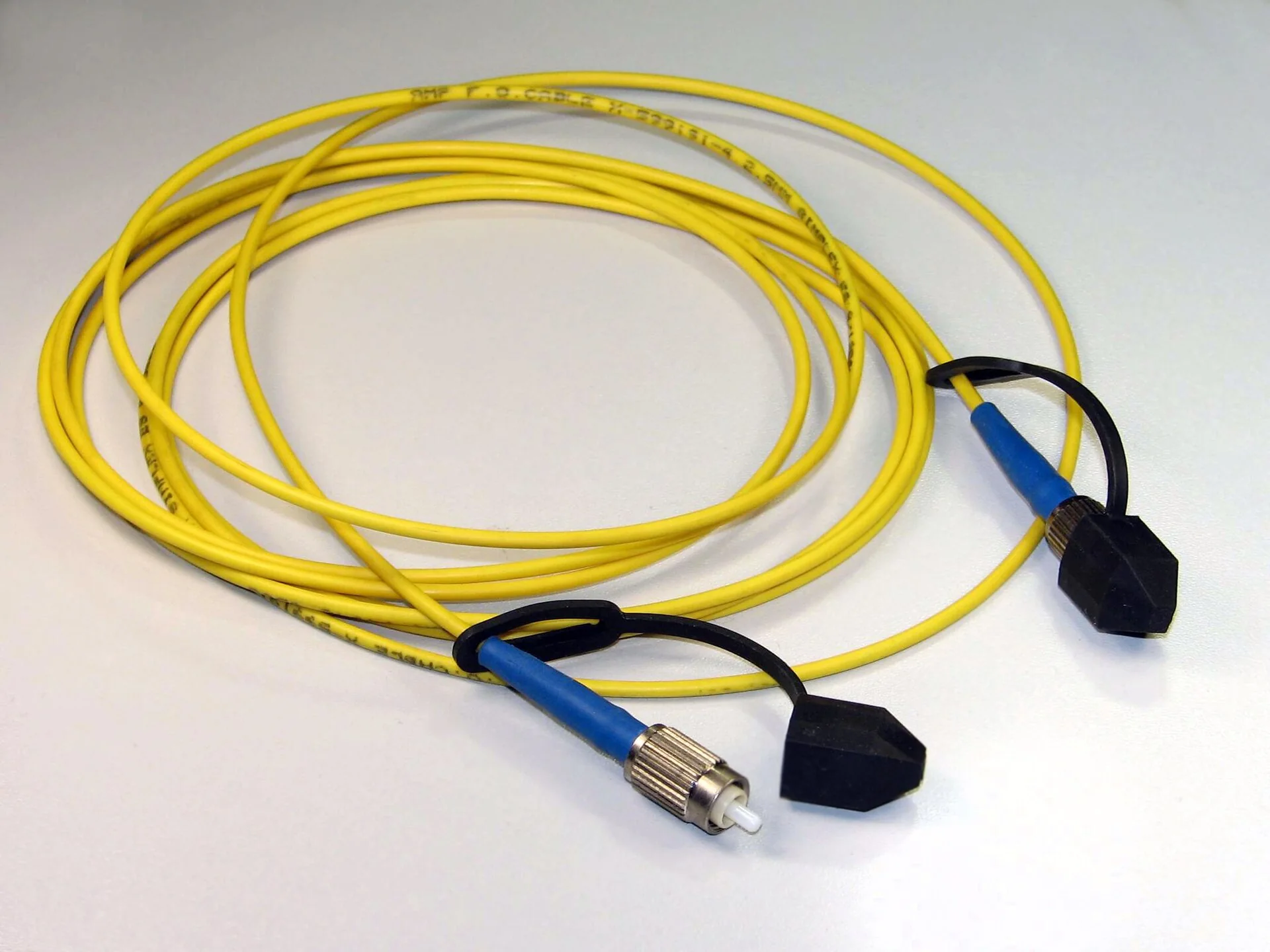
Optical patch cords connect equipment and termination points. Their connector format must match the interfaces: see the ST-connector patch cord in the gallery.
Optical connector quality and cleanliness affect link loss. Bend radius and pulling tension must follow the manufacturer’s specifications. Fibre slack is stored in appropriate holders, with labelled terminations.
Your provider’s Internet service may use fibre, while devices in the rooms use Ethernet over copper. An indoor fibre backbone serves a different need. The scope of work, access and any work on the provider’s equipment must be specified in the project.
Network, Wi-Fi and security
Cabling prepares the connections. Coverage, settings and security features then depend on the equipment and its configuration.
Planning a jack near the access point lets you choose its location based on the spaces to cover. An access point connected by Ethernet can carry its traffic over the wired network instead of relaying it only by radio.
Placement depends on walls, floors, obstacles and the number of users. Cable doesn’t replace a coverage survey or Wi-Fi settings.
With compatible equipment, PoE powers a camera, IP phone or Wi-Fi access point through the Ethernet cable. Check the power level required and the budget available on the switch or injector.
The number of devices, link quality and installation conditions all matter. An RJ45 jack doesn’t automatically supply PoE: the source and the device must be compatible.
Planning and execution
Every building has its constraints. Defining the steps and deliverables in the quote tells you what will be installed, tested and documented.
Identify rooms, workstations, devices, existing cabling and future needs. Locate the central point and possible access in the building.
Define jacks, pathways, distances, cable type and equipment. Plan the work and any finishing.
Use suitable routes and supports. Follow manufacturer instructions for pulling tension, bend radius and installation environment.
Install jacks and panels, terminate compatible components and label both ends of each link.
Carry out the tests defined in the quote. Distinguish termination checks, qualification and certification.
Deliver the labels, port map and results set out in the contract. Clarify device connections and available spare capacity.
Every environment is different
Access, height, routes, outdoor conditions and occupancy hours all affect the installation method. For an occupied site, plan the network cutover time and the equipment involved. Finishing work and work on existing services must be specified in the quote.
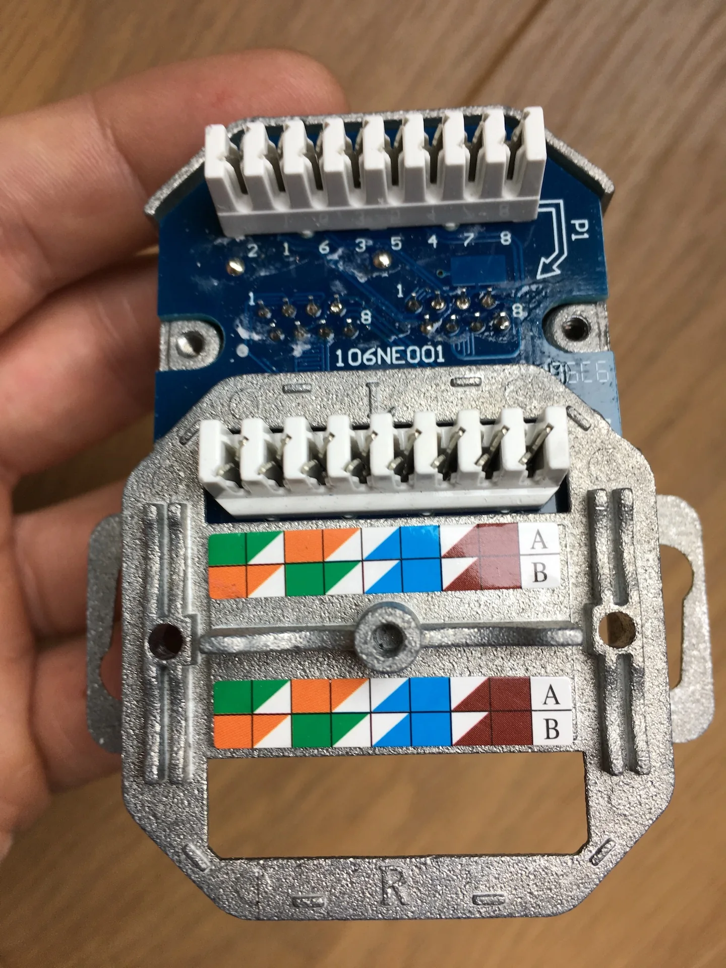
See the termination equipment in the galleryTesting and installation handover
Not all tests measure the same thing. The level of testing and the expected reports must be defined before the project starts.
Check the wiremap and, depending on the tester used, look for broken wires, shorts or reversals. This verification is not, on its own, a category certification.
Assess a link’s ability to support a given network application. The result depends on the type of tester and test protocol used; it doesn’t automatically replace a standards-based certification.
Measure the parameters required by the chosen standard and link type with a suitable tester. The contract must specify the category, test limit, method and expected report for each link.
Illustrative documentation example
| Zone | Jack | Panel port |
|---|---|---|
| Office 01 | R-01 | P-01 |
| Meeting room | R-02 | P-02 |
| Access point | R-03 | P-03 |
Identifiers, testing level and results to deliver are defined for your project. This table shows a labelling principle, with no test results or certification.
Optical loss measurements assess the light transmitted through the link and are compared with the link budget. An OTDR can help locate events such as a connection, a splice or a fault. These tests are complementary and their need depends on the project.
Number of links, jack labelling, panel mapping, category or fibre type, testing level and results format. If certification reports or optical measurements are required, they must be explicitly included in the contract.
Technical references: Fluke Networks — testing levels, FOA — fibre testing and OTDR. The tests offered and the measurement equipment are confirmed in the quote.
Existing network and upgrades
An existing network can be kept, extended or put back in order after an assessment. Finding the source of a problem avoids replacing parts that work.
Check the patch cord, the jack, the termination, the switch port and the fixed link. Symptoms can come from the cabling or a device: a diagnosis helps target the work.
Check free ports, routes, distances and PoE capacity before adding jacks. An expansion may require more than an extra cable if the central point is already full.
Identify destinations and active connections before moving patch cords. Plan a staged cutover, keep the port mapping and update the labels after the changes.
Tell us the type of building, the number of jacks or devices, the rooms involved, available plans and the existing network. A few photos of the telecom room and accessible routes can help prepare the assessment. Also mention your bandwidth goals, timeline and occupancy constraints.
Your installation starts here
Home, office, store or large building: tell us what you want to connect. Let’s plan the work and steps suited to your installation.
contact@solutionalarmeplus.caDon’t have all the details? Just describe your project.